build diary
<< | show individual entries | >>May 4, 2004:
Nothing exciting, just a little more time spent reworking the holes for the gauges.
They've got a beveled edge now so the gauges look like they belong. I need is some plastic to cover them and I'll move on.
CMC did another 2-day build at the Walter Mitty vintage event and even managed to drive the car on the autox course as well as partway home. Impressive. A conversation with CMC did reveal some new information, though. If the front of the diff is not hard mounted to the frame, it'll cause problems with a loss of drive as the diff moves around. I can't think of how this works and Steve didn't really seem to know either. The only theory that I and my coworkers have come up with is that the driveshaft is pulling free of the splines in the transmission but that doesn't seem plausible. A diff will work at any angle. He described a clicking when trying to go uphill. Strange....The existing mounting technique works for a while but eventually loosens. I may try using a locking nut on that long bolt on the diff if I can't easily work out a mount on the frame itself - after all, if it works when it's first put together, it should continue to work. But the new frames are being shipped with a hard mount for the nose of the diff instead of the rubber one I have now. Time for some mulling-over in the garage.
In further news, the remaining bits and pieces of my setup should be shipping tomorrow. I'm moving towards the point where I can paint the body panels - that will be exciting!
entry 272
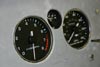 After a bit of reworking of the holes, the instruments look more integrated.
It's hard to photograph this!
entry 273
May 5, 2004:
I've polled the Grassroots Motorsports forum about the differential mounting.
One good suggestion was to build a PPF out of tube - or at least a skeletal version of one. This isn't going to work without changing the shape of the transmission tunnel, however. The real question is whether it makes any significant difference to have the diff mounted to the frame - and thus put the torque loads through it - or have a PPF substitute. The former is obviously easier. Steve has informed me that he'll be sending the new bracket to me to weld into place. I guess it's time to wire the garage for 220v!
There is 4" of splined shaft at the end of the driveshaft so I doubt the CMC-built cars are pulling the shaft free. Puzzling.
entry 274
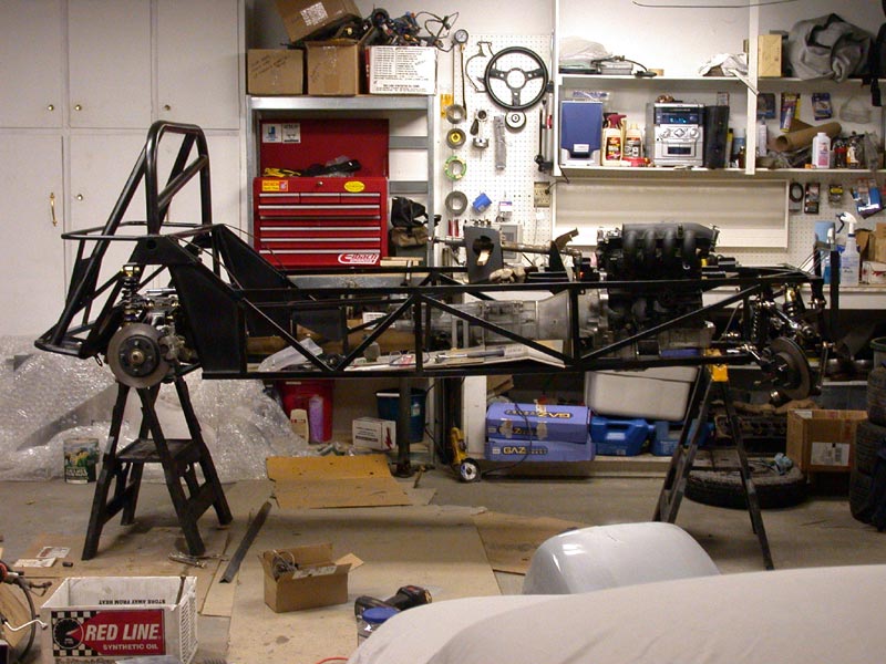
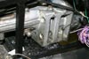 For those who are helping me work out the various questions about bracing the diff - here is the rear mount for the transmission.
The vertical tube on the transmission tunnel is directly behind it.
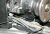
entry 275 The current diff mounting.
entry 276
May 6, 2004:
Lots of differential design going on!
This is fun stuff. Lester Seal reports that he built an E Production Miata that didn't have a PPF. His solution was to run a short piece of tube forward from the top of the diff and anchor that. It was triangulated with a tube coming up from the bottom of the diff. This reportedly worked quite well, and an upside-down version could certainly be adapted to the Seven. It's also something that could be retrofitted so I'm going to try simply putting in a hard mount in place of the rubber bushings I have at the moment. Combined with a proper locking nut that should prevent any movement. It's also very light (I have some aluminum spacers to replace the rubber) and easy. I figure I'd rather put the existing mount into compression than try to hook something up to the bottom of the frame and have it in tension.
This is interesting. They're basically intended to bypass the bushings in the diff mounting arms to give a more solid mount. A shiny version of my Shoe Goo and the plastic inserts I'm using now. I can't see how it benefits a Miata but I was actually considering exactly the same thing for the Seven yesterday before these were brought to my attention!
I've also been looking at the driveshaft angle. I've got the nose of the diff too high at the moment - it really should be parallel with the output shaft. It's a good thing I was looking at the diff and caught that.
entry 277
May 7, 2004:
I didn't have a chance to do any measuring of driveline angles last night.
However, I did order my brake and clutch pedals and hydraulics as I figured it would be easiest to run the lines before the engine goes in. I'm pretty excited about this!
entry 278
May 10, 2004:
Lots of work this weekend.
First, driveline angles. I suspect all of CMC's engineering has been done with the smaller 1.6 diff, but even then a mounting point that is about 1" higher would make a big difference. The bottom of the bigger 1.8 differential hits the frame before the diff gets level, and the longer nose of the 1.8 also means the driveshaft is shorter. Thus the driveline angles in my car are now are as good as they can be but still not ideal. The driveshaft angle is a touch under 4 degrees and the diff and transmission output shaft are about 3 degrees out of alignment. I'll see how this works - if there are vibration problems I'll remount the diff higher up in the frame.
I've talked to a couple of engineers about the rear diff mounting as well. They are unanimous in condemming the existing mount for the nose of the diff. I'll have to make a stumpy version of a PPF to fit inside the frame. This could be a bit of a challenge, but it should be worth it in the long run. Lester Seal has the correct idea with his plan to use the PPF.
In other news, I've cut out the bottom of the dash for more legroom. The dash is looking good although my first attempt at some glass to cover the gauges was pretty hideous. I also riveted the rear bulkhead body panel into place - I've been looking forward to doing that for some time! It's the best fitting body panel so far. It needs one small bend at the bottom and two notches needed to be cut out of it, but all the angles appear to be square and it looks good in place.
entry 279
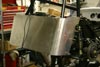
 There's a limit to how low I can drop the big 1.8 diff.
You're looking at the bottom of the diff meeting the frame. I'd shaved this down a little since the photo was taken but there's only so much meat that can be removed.
entry 280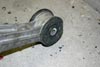 In order to level out the differential as much as possible, I shaved down the steel inserts inside the diff bushings.
It helped.
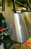
entry 281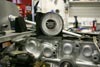 A great way to measure the output angle of the transmission.
entry 282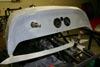 The dash has been reshaped for leg clearance.
entry 283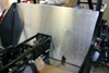 I'll call this panel the rear bulkhead for lack of a better name.
It's the best fitting panel of the lot so far. I needed to cut two notches to allow access to the front bolts for the lower control arms, otherwise adjusting the alignment would be difficult.
entry 284
May 11, 2004:
I started installing the rear sheetmetal last night.
The passenger's side went in pretty easily, but I hit some snags with the driver's side. More information to follow...
entry 285
 Beginning to install the rear sheetmetal.
entry 286
May 14, 2004:
The problem with the rear body panel was alignment on the driver's side.
I had an inkling this might be a problem, but I thought it was due to a badly cut panel. That wasn't it - the round tube that forms the upper portion of this body is welded on crooked. You can get a hint of it in photo 87 - the driver's side is higher than the passenger's. It's not bent as there's a consistent angle from one side to the other. I'll either have to make a matching, crooked rear panel or cut those parts up and reweld it. This has prompted me to measure a few other dimensions on the frame, as you might expect. I got a bit of a scare when the wheelbase came out 1" longer on one side than the other but this was tracked down to a rod end that wasn't installed quite as far as the others. A few other measurements are showing up 1/4" out here and there, but nothing crucial as yet.
My brake and clutch pedals have also arrived! This was a fun day of unpacking white Wilwood boxes. I'm going to have to modify the frame in order to fit these. Time to wire the garage for 220v, then. I'm using twin master cylinders for the brakes with a balance bar. I've also got an adjuster so that the bias can be tweaked from the cockpit. I'd rather not have to get inside the driver's footwell to adjust the bias once everything is installed!
entry 287
 Uh-oh.
That's not how things are supposed to line up. Look at the cutout for the shock mount as well as the bottom tube.
entry 288 Brake pedal and masters!
entry 289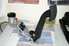 Clutch pedal and master!
entry 290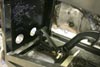 The brake pedal in place.
It'll take some modification to get this mounted.
entry 291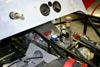 Playing with switch layout.
That's the ignition switch and starter button. The blue knob is the brake bias adjuster and it's going to go over by the handbrake lever. I figure that if I'm adjusting the bias while driving, I won't want to accidentally turn off the ignition...
entry 292
<< | show individual entries | >>