build diary
<< | show individual entries | >>May 17, 2004:
A fun weekend of playing with brakes.
The frame surgery has been done and it worked out quite nicely. In the next few days I'll put together a reinforcing plate to replace the parts I had to cut out. It should be a nice clean setup when I'm done. Now that I have the pedals in place I can start finalising the rest of the driving position. Happily, there's even enough room in the footwell for me to wear normal shoes. I'm not sure if I'll be able to work out a dead pedal of any sort. I also have to find a couple of pipe to flare adaptors - for some reason, the Wilwood master cylinders have pipe fittings on them. That seems a little odd but there may be a good reason. I'm used to dealing with flare fittings for the brakes.
A bit of a puzzle. CMC put a small bracket on the frame that's intended to be the junction between the clutch flex line and the hard line. It's placed in a similar location to the Miata one - but the Miata has it quite a bit higher. I realised that the factory bracket could be bolted on the firewall on the other side of the engine, giving a nice clean install that still leaves enough room for significant engine movement. This makes the hard lines easier to route and tidies up the engine bay. I'm pretty happy with it.
entry 293
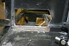 In order to fit the pedals, the frame needed a little surgery.
entry 294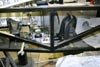 The pedals in place!
entry 295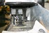 The final location of the gas pedal will be finalized when the brake system is plumbed.
entry 296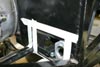 To reinforce the frame where it's been cut away, I'll be welding a plate into place.
Here I'm working out the dimensions.
entry 297 The master cylinders.
Those brake masters have bigger reservoirs than is necessary, but I'd rather have too much fluid than too little! It was also a matter of bore sizing and availability.
entry 298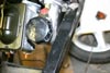 There's not much clearance between the clutch master cylinder and the frame - but there's enough.
entry 299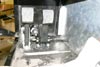 The balance bar for the brakes can be adjusted remotely.
You can see the cable running through the transmission cover.
entry 300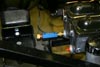 In order to use my residual pressure valve (required because of the low mounting of the masters), I'm going to have to be a little more creative with the plumbing.
The motor mount is in the way!
entry 301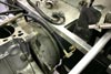 The clutch hydraulics.
For some reason, CMC put a bracket for the clutch flex line on the passenger's side of the transmission tunnel. I'm not sure why. This is close to the Miata location, but it's much higher on the Miata. To use this on the Seven would mean the clutch line would be fairly convoluted. I found that bolting the factory bracket to the firewall on the driver's side made the installation much cleaner and simpler.
entry 302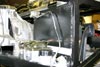 The clutch system is done.
This line is very three-dimensional and the bends make a lot more sense when you see it in person!
entry 303
May 19, 2004:
A stop by my local hydraulic store yielded the pieces I needed to put together my braking system Last night I managed to get most of the lines done but I'll still need a tee to join the two front brake lines.
If I'd been thinking, I would have specified my custom front lines to have a junction block on the left side. But the tee will do the trick. One of the lines will have to wait until the test transmission gets removed as it's a little awkward to reach. But I'm getting close to the point where I can bleed the system, and then I'll find out just how hard that pedal is!
Some of my replacement parts showed up from CMC yesterday. A new nosecone - which on initial impression seems to be made with thicker fibreglass than the original - was joined by front cycle fender supports and some unwelded upper rear control arms. The unbent transmission cover slit the box open and escaped. Whoops! I've decided that my Miata will lose its engine this weekend so that I can kick-start the progress on this critter. I'm getting eager!
I'm not playing with the diff at the moment, but I did see some interesting photos of an SR20DET-powered Miata that snapped the rear mounting arm off the diff. There's obviously a lot more power involved but it does illustrate what can happen with a bad mounting setup. Here's the diff and here's some more information on the car.
entry 304
 Bits from CMC!
The front cycle fender supports, replacement upper rear control arms and a new nose cone have shown up. I'll be welding the arms together for a perfect fit.
entry 305
May 21, 2004:
The plate is now ready to be welded in place.
I'll also do a couple of other small jobs that need attention such as the seatbelt mounts. Of course, first I need a welder in the garage. I shudder to think where that might lead! The shell engine has been removed from the Seven frame, and the first step in getting the various engines shuffled around has begun - Bill's Miata is getting a new engine, freeing up the one intended for my Miata, which will make the 11:1 engine available. Phew.
Someone on the Locost mailing list suggested using a motorcycle muffler. There are stock sportbike mufflers all over eBay for next to nothing. Hmm...
entry 306
May 23, 2004:
Whoops - left the memory card for the camera at work, so no photos yet.
The garage has been wired for 220V, the reinforcing plate is welded in place, new seatbelt mounts have been welded in to replace the incorrectly located ones - and the tube that forms the back of the rear body has now been properly aligned. This latter job had me swearing, as it required the removal of the gas tank again and this is a VERY tight fit now that the rear bulkhead has been riveted into place. I'm not looking forward to having to reinstall that once again. It would have been a lot easier to start with a frame that wasn't crooked. It's too bad I didn't have the camera, as the Hi-Lift jack was brought into play to help "massage" everything into place. Add another use for the Hi-Lift - welding clamp! A quick test fit shows that the rear panel will now fit correctly. Because I was dealing with supports that had been straight before, one of them is pretty ugly now that everything else is in alignment. Hopefully this will be well hidden by the gas tank once that gets reinstalled. First I need to repaint the welded areas.
I also picked up a pressure switch for the brake lights. The first cruise through the parts catalog unearthed the perfect candidate - the same one used on all the British cars in the 60's, including my Land Rover! I've even got a spare one of those but it's been through a fire and I don't trust it. The cool thing about that would have been that it's probably the same switch used on the Lotus Seven during that time period. I did decide to get one from 50's Detroit iron instead, as it was both cheaper and in stock. It just means I'll use bullet connectors instead of spades - odd, given that Lucas really liked bullet connectors.
entry 307
May 24, 2004:
The new upper control arm has been spot-welded together and a few other touches have been done.
I'm already ready to repaint the modified areas and reinstall the gas tank. I feel like I'm actually making progress here.
entry 308
 The brake light switch in place.
entry 309 The relocated seatbelt mount.
This is where it was supposed to be installed but the welder had a bit of a senior moment and put mine in the older location below the cross bar.
entry 310 Having the welder in the garage allows me to build little touches such as this support for my residual pressure valve.
I'm a little obsessive about supporting brake lines.
entry 311 When I realigned the rear cross bar (I don't know the "official" Locost tube number), one of the vertical supports no longer lined up properly.
It's ugly but it should be hidden. Now my rear body panel will fit and the car will look more symmetrical.
entry 312 The replacement control arm from CMC was sent in two pieces so that I can weld it into the exact alignment for my car.
In order to get everything properly set up, I did have to move the forward rod end (on the left of the picture) out a bit further. But now the arm is nicely centered and everything is in place.
entry 313
<< | show individual entries | >>