build diary
<< | show individual entries | >>February 5, 2004: 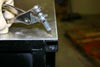 Cleco fasteners were used to hold the floor in place as I started drilling holes.
They're easily removed so I could move them around.
entry 88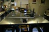 To prevent the floor from shifting or buckling as I drilled, I spaced out the holes.
A series of 5 holes in a row would be drilled in the order 1-5-3-2-4.
entry 89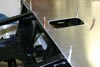 Once the clecos were holding everything down well, I used a centerpunch to locate each hole.
They're 1 inch apart.
entry 90 I just like this photo.
entry 91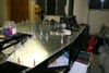 Partway through drilling 300 holes.
I'm moving the clecos around so the panel is well located in the section I'm drilling.
entry 92 Once every hole is drilled, I removed the floor to deburr the holes.
It looks like my measurements were pretty accurate and I hit the middle of the tubes. Whew!
entry 93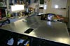 The rivets were installed in the same order as the drilling.
I've only put in every second rivet along the sides as I'll use the others to help hold on the unstressed bodywork.
entry 94
February 7, 2004:
A lot of people are watching this build!
I love to hear from you. And congrats to Geoff Davis, who just took delivery of his own CMC Miata kit. He'll have a website up before too long, I'm told. Apparently the wait time from CMC is now over 3 months.
Well, my ski trip today got cancelled when the Caddy wouldn't start (20W50 gets pretty thick in the cold), the Miata proved to be frozen to the car cover and my Subaru has a dodgy ignitor. And that set the tone for the day.
I bolted up the diff and flipped the car back over. Hopefully it will never be upside down again! Then I started cutting thrust washers for the rod ends. 32 of them, all which had to be within about 0.5mm of the correct length so that I wouldn't bend the brackets when tightening suspension bolts. CMC sent some pipe for creating these, but they only sent enough pipe almost do three corners of the car. Luckily, my local hardware store has short lengths of pipe in the correct diameter and thickness. A bit of an annoyance - but not as much as when I went to bolt up the control arms and discovered that the rod ends don't sit in the middle of the brackets! Argh. So I have to recut a bunch of the washers. This is probably one place where the GRM build had access to prepared items to speed things up!
More disturbing was the discovery that the right rear upper control arm is the wrong shape. I can modify it to fit but I want to make sure I don't end up with a slightly different length control arm on one side of the car than the other. It might also affect the bump steer in the rear - I'll have to do some measuring. Putting the left side arm on upside down made for a perfect fit, so it's the arm and not the slightly asymmetrical brackets causing the problems. It's still more accurate than if I'd made it, probably. On top of this my digital camera was throwing fits and I had a hard time getting photos. You'd think they'd last for more than 15,000 shots!
Still, at the end of the day I've made some progress. The car has suspension on three of the four wheels, the diff is in and the uprights are bolted in to place. I can now spin the wheels by hand through the diff! I mounted the front shocks upside down to keep the unsprung weight as low as possible. It'll probably cause no end of questions so I might put them back upright. The steering rack is also mounted in place and I'm getting ready to run the steering column. Hmm, I'd better get a test engine in there first so I don't accidentally put the steering through the water pump or something...
entry 95
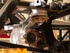 The diff is in.
The big 14mm bolts I bought didn't fit through the small 12mm holes in the frame and the diff retainer. I wanted the tight fit through the diff bushings so I enlarged the holes!
entry 96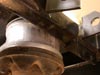 A small bit of grinding was needed to squeeze the diff into place.
entry 97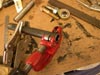 Cutting thrust washers for the suspension.
This involved a lot of careful measurement.
entry 98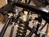 After all that cutting (32 washers!
) I installed the control arms - and found that of course the width of the arm changes the location of the rod end. So about half of the washers have to be redone. Sigh. And yes, the shock is mounted upside down to lower the unsprung weight.
entry 99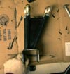 This is not good.
The two upper rear control arms have different geometry! One fits into place perfectly, one does not.
entry 100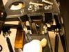 The offending control arm.
These brackets are actually 5mm futher back than the ones on the other side of the car as well.
entry 101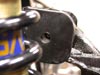 With some juggling of rod end placement, I can get the arm attached to the car.
But then it's misaligned (and skewed sideways) on the upright. A slotted hole would solve the problem here. I need to make sure the geometry hasn't been changed.
entry 102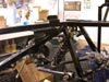 The mystery bracket.
I thought it was for steering, but that's not making any sense unless I put another universal joint in place. There isn't one on the other side of the car.
entry 103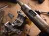 Getting ready to install the steering.
Since I don't have the key for the donor, the ignition switch (and steering lock!) weren't doing me any good.
entry 104
February 10, 2004:
Steve at CMC is going to send another rear control arm to replace the one that's off.
As someone who deals in complex, essentially hand-made turbo kits I'm not surprised to find small problems like this - particularly in an early version of a product. So far, none of the problems have stopped me from working on the car.
A componentry update. Miatas use the same steering column splines as Subarus. A co-worker gave me an unneeded steering column adaptor from a Subaru steering wheel (he put the wheel in his Corrado) and it fits perfectly. I'll have to make a plate to adapt the OEM Subaru flange to my Mountney wheel, but that's simple. It will also give me the ability to space the wheel forward and back depending on the thickness of the plate. The Miata brake flex lines aren't going to work with the frame so I'll have to get some custom ones made. There's a decision on the "OEM vs stainless steel" quandary and another few bucks for cost. When working on the wiring harness last night, I also realized that I'll need to get a set of coils from a 1.8 Miata instead of the 1.6 ones I have. The 1.8 ECU won't drive those 1.6 coils. Yes, it would be easier to use the 1.6 ECU. But I have plans for down the road. Oh, and that mystery bracket is for the steering shaft. Fair enough, I'll make that work!
entry 105
February 11, 2004:
While I didn't make much real progress last night, it sure looks like it!
I brought home a bunch of engine parts to test-fit the drivetrain. Nothing actually works - I brought home a broken transmission, an empty block with an oil pan on it, a damaged head and a contaminated intake manifold - but it's all fairly grime-free and therefore looks nice. I'm trying to get a feel for the driving position before I mount the steering column. This all stems from the pedal locations. Once I've got that, I'll have an idea of how far back I sit. Then I can place the steering column and the shifter. There are several inches of adjustibility in the motor mounts.
I've also been looking at seats. There aren't a lot of options for such a narrow (17.25") tunnel. Cobra makes one called the Roadster 7 that is built for 7-esqe cars and I'll have to find a price for them in the US. Otherwise, I might just modify a stock Miata seat fairly heavily.
entry 106
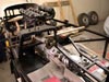 I dropped in some spare drivetrain parts to help set up the driving position.
entry 107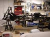 The engine sits a long way back in the car.
entry 108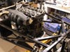 There's lots of room to access the front of the engine.
Service will be easy. As you can see, there are a few parts missing here.
entry 109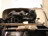 Not much clearance for the intake manifold here.
entry 110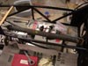 Yes, the driveshaft does need to be shortened a bit.
entry 111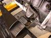 A motor mount close-up.
entry 112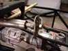 The Subaru steering wheel adaptor.
entry 113 Test-fitting the throttle pedal.
entry 114
<< | show individual entries | >>