build diary
<< | show individual entries | >>April 19, 2004: 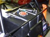 The tank is in.
The upper straps are 1/16" aluminum.
entry 242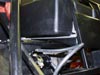 The fuel filter is installed.
The pump will be strapped just above it.
entry 243
April 20, 2004:
I had been concerned with the sizes of the fuel lines, given that the Miata runs on 5/16" and the tank has a 1/2" outlet.
It turns out that my fears were unfounded - the pump has a 1/2" inlet and we have the adaptors on the shelf at Flyin' Miata to make the outlet 5/16". That was resolved far more easily than I expected! I'm also going to use fuel hose to feed the engine instead of bending up hard lines. While manufacturers use the latter, I suspect it's not for performance reasons.
entry 244
April 21, 2004:
More fuel line work.
I needed about 18 feet of 5/16" line in total (9' for the feed and the same for the return) as well as maybe 18" of the 1/2". It's all looking pretty good.
To ensure that I don't have problems fitting the lines past the transmission, I've put another transmission and dummy engine in the car. It's impossible to get anything past the bottom of the tranny on the right side which is unfortunate. But I've worked out routing for everything that will keep the wires from chafing as well as keep them clear when the transmission is being removed or installed. I did decide to cut one of the rubber mounts for the rear of the transmission down by about 3/4" as it was putting the tail of the transmission too high.
entry 245
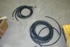 The nice thing about working at a performance shop.
I need fuel line, but I'm not sure how much. So I brought home 60 feet of it.
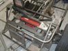
entry 246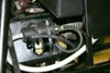 The fuel line routing.
While the pump mounting looks a little cheesy, this does work quite well. We do the same thing on some of our turbo Miatas.
entry 247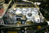 Another dummy engine in place so I can do fuel line and wire routing and don't accidentally put the main power feed through the transmission, for example.
This time I've mounted some accessories.
entry 248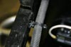 These cool little mounts are what I'm using for wire and hose management.
A 1/4" hole and they pop right in. A ziptie fits though. I can't ziptie right around the frame rail because there are often body panels riveted to the other side.
entry 249
April 22, 2004:
Not too much work done last night - I finished the last two fittings on the fuel tank.
The return line is now hooked up on top and the extra pickup has been plugged. Most of my time was spent working on getting my Cadillac ready for a trip to Vegas this weekend.
CMC appears to have dropped off the face of the earth. Their phone line no longer takes messages and emails are not being acknowledged. I could repair the broken/sawn nose cone that was shipped to me, rework the upper control arm and transmission tunnel cover that didn't fit and make my own cycle fender supports so I'm better off than the folks who are still waiting. One person just contacted me and says that their frame arrived on April 8th after being ordered in November! Steve at CMC seems like a good guy but he's having trouble keeping customers informed. Even just hiring a temp to cover the phones would go a long way towards keeping customers happy...
entry 250
April 27, 2004:
Yes, I had a good time in Vegas.
Thanks for asking. It appears that I may have made a mistake with my 1.6 automatic TPS. The signal is a 0-12v signal as opposed to the 0-5v one my ECU wants. Oh well.
Update: turns out I was mistaken about the TPS. It's okay.
Lester Seal is doing some interesting things with his build. He's moved the differential back and up, will hopefully be using a modified Miata Power Plant Frame and is working on a dry sump. He also reports that Leslie is back in the office and CMC is starting to return phone calls. Good!
entry 251
 Lester Seal's modifed differential mount to move the diff up about 1.25" and back 2".
He's also modified the frame to fit the Miata Power Plant Frame.
entry 252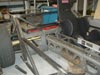 Lester's PPF.
I'm not sure there's room for a passenger anymore, but the PPF sure looks good.
entry 253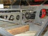 Another view of the PPF mount and the frame modifications.
entry 254
April 29, 2004:
Whoops.
I looks like I might have a problem. My steering is now set up with the rod ends above the steering knuckle. But when I set up the location of my steering rack, I believe I measured as if the stock ball joint was being used, and that hangs below the knuckle. The tie rods are visibly at the wrong angle and I suspect the current setup has massive amounts of bump steer. I'll have to do some measuring to determine is this is the case or not. Simply moving the rod end so that it's below the knuckle causes problems due to the extreme angle of the attachment - at least when the suspension is at full droop. Both the rod end angle and clearance of the knuckle are a problem here. I'll have to do some thinking about how best to resolve this. Going back to Miata ball joints and more normal rod ends would certainly work, but then I'd need new steering knuckles because the tapered hole has been drilled out. Raising the steering rack will also cause problems with the angle of the rod end. Sigh. I'll find a way to make this work. Hopefully without having to spend too much time machining the knuckle. I can see now that it would have been simple to just keep the factory ball joints and extend the tie rods. Not that I had any straight tie rods to extend! I'll try to get some photos soon of the problem.
I started test-fitting a few of the body panels last night. There are some extra bends needed (no big deal) and one of the panels needs a little tweaking to clear the neutral switch on the transmission. The switch protrudes just a little bit too far to be covered by a flat panel. They fit reasonably well, but not as well as I'd expect from a CNC plasma cutter - the patterns need some work. This has been true of every aluminum panel I've tried so far. Basically the angles aren't quite right or holes are offset. Nothing that's going to leave a visual mis-match so it's only an irritation when I'm assembling. While I certainly saved a lot of effort by buying the panels pre-cut, I probably would have obtained a better fit by cutting them myself.
Update: after a bit of perusal of the FK Bearing catalog, I found a high-misalignment version of the bearing I'm using. It'll give me an extra 7 degrees of rotation as well as being slightly longer - both of which are good. It's also going to clear the knuckle better due to a lip on the ball - and to top it all off, it's rated for 5,000 lbs greater axial load. The downside is that they're about $20 each, almost three times the price of my earlier choice. Part number HJMX7T if anyone's interested.
entry 255
April 30, 2004:  One last view of the PPF modification by Lester Seal.
The passenger compartment is not as compromised as it appeared in photo 196. He reports that he will be using 1/8" steel plate on the passenger's side upright to replace the 3/4" tube that he's removed.
entry 256 An example of the fit of the aluminum body parts.
Lester informs me that his are the same way. Once the transmission cover has arrived, I'll make sure it's bent well enough to cover this up nicely.
entry 257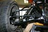 A blurry photo of my bad steering geometry with the rod end on top of the knuckle.
entry 258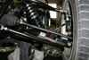 The corrected steering geometry.
entry 259 The original rod end didn't deal well with this sort of angle.
I'll do a little grinding on the knuckle as to clear the threads. This is at full droop so it's a worst-case scenario.
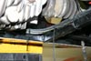
entry 260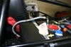 The fuel return line.
Okay, it's not the prettiest. I'll have to see what I can do about this. Maybe a couple of feet of braided stainless line just for this section...
entry 261
May 3, 2004:
Busy weekend!
I spent some time finishing the wiring in the rear of the car and working on routing. It's all looking nice and tidy although I still have to work out the connectors for the taillights. This will be easier to do when the tails are mounted - I learned the hard way on my Land Rover rewire that just adding in extra wire "because I might need it" makes for a very messy harness.
I've also started on the instruments. I'm not completely happy with how they look right now, but there's always the chance to change them later. I really don't want the car to look as if I simply stuck a factory gauge panel into the dash, so I'm taking pains to hide the "Miataness" of the donor panel. It meant a lot of grinding and careful shaping to get as far as I did. If I paint the dash black it'll look more integrated but I was rather hoping to stick with body colour. We'll see.
Typically the way you build a car like this is to install the engine and transmission very early on. Because I'm still waiting for my engine, I'm having to work in a bit of an unusual order. The logic of when to install what body panel is a little complex, but the good thing is that I'm working with a mind towards how the engine will be installed and removed easily.
entry 262
 The wiring at the rear is coming together.
I'd rather not have the axle chew into this, so I'm being careful to keep it all well tied down.
entry 263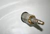 Not a bad measurement - the steering column hole has been drilled in the scuttle.
entry 264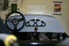 Working out the placement of the instruments.
They're not centered on the dash because the tach would be covered by the wheel and the offset transmission tunnel would look a little strange.
entry 265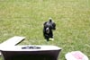 I'm taking care of Turbodog for the week.
He seemed to think that I had better things to do than cutting holes in fibreglass.
entry 266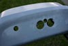 Holes are cut for the instruments.
I had to enlarge the holes freehand and I screwed up on the speedometer. Nuts. I'll try to patch that up with some bondo.
entry 267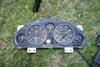 The modified instrument cluster.
I even wound the odometer back to 0.
entry 268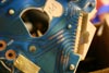 This is interesting.
The Japanese "Miata" (the Eunos Roadster) comes with a 180 kmh speed limiter. It can easily be disabled by removing a screw. Looks like the US instrument cluster is the same part. What do you think would happen if I put a screw in there on a stock car?
entry 269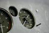 A closeup of the instruments.
I was thinking about mounting the chrome ring to the dash itself - that might have looked better, but it would have been difficult to add glass later. The mounting bolt is just a temporary one as I will find something that looks a little better.
entry 270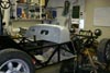 Hmm, it's starting to look like something.
entry 271
<< | show individual entries | >>